In this article I will try to explain the basic engineering that limits graphics card coolers. I will go through the basics of heat transfer, the basics of fluid mechanics and some basic math/physics to explain the 'Blower coolers are bad' paradigm.
A word on blower vs axial coolers, a response.
I recently tried to explain the physics behind what the limitations of blower coolers compared to axial coolers are in a thread and don’t want this answer to get buried … so I’m posting it as a separate post here.
First, we
need to establish what heat/energy transfer even is and what factors play a
role in how much heat/energy can be dissipated by a cooler. To show this I’ll
first explain the general concept of a transport equation.
Something
being transported = coefficient * characteristics of a transport medium/area of effect *
driving force
----------------------------------------------------------------------------------------------------------------------------
Let’s look
at what path our energy or heat is going to take and through which layers it
needs to pass through
The hottest
point is going to be the chip itself since it is the heat source.
On top of
the chip is a very thin layer of thermally conductive paste, liquid metal or a
graphite pad. If we look at the packaging of thermal paste, we will find a performance
rating on it stating a number and W/mK which is a rating for thermal
conductivity. A high number means high conductivity which is good for a cooler.
Thermal paste usually has a thermal conductivity between 2 and 15 W/mK, compare
that to copper which has a thermal conductivity between 240 and 380 W/mK. Just
by comparing those two numbers we can already see that it is beneficial to use
as thin a layer of thermal paste because its conductivity is way worse compared
to copper.
Next the
heat/energy must pass through either A) a heat spreader or B) directly into the
heat pipes / vapour chamber.
A heat
spreader is nothing but a plate of copper with the purpose of increasing the
surface area of the hot spot. Therefore, the name heat spreader, it quite
literally spreads thermal energy.
A heat pipe
or vapour chamber both use
There are two types of transport that we will look at today. Thermal conduction and thermal advection.
Thermal conduction is the transfer of heat between atoms next to each other whereas thermal advection is tracking the properties of a fluid while it is moving. Both describe heat exchange and both will be needed to describe the basics of coolers.
Using advection to determine the power draw or cooling power of a cooler is quite easy. All you need to do is to measure how much fluid (air in our case) passes through the cooler to determine the massflow. This can be achived with an aneometer and the known denisity of the air at the measured temperatre. Speaking of temperature, we also need to measure the intake temperature as well as the exhaust temperature. The only information that is missing now is heat capacity (assuming constant pressure).
If we now arrange all of our variables in terms of a transport equation we get the following
Energy transferred to the medium = massflow of air * heat capacity of air * temperature difference between the intake and exhaust
or
Q = m * cp * dT
Now that we know how much energy we can dissipate we therefore know how much energy needs to be conducted through the cooler itself. Heat conduction follows Fourier's Law and can be easily explained when you imagine an iron rod.

-----------------------------------------------------------------------------------------------------------------------------
There are two types of transport that we will look at today. Thermal conduction and thermal advection.
Thermal conduction is the transfer of heat between atoms next to each other whereas thermal advection is tracking the properties of a fluid while it is moving. Both describe heat exchange and both will be needed to describe the basics of coolers.
Using advection to determine the power draw or cooling power of a cooler is quite easy. All you need to do is to measure how much fluid (air in our case) passes through the cooler to determine the massflow. This can be achived with an aneometer and the known denisity of the air at the measured temperatre. Speaking of temperature, we also need to measure the intake temperature as well as the exhaust temperature. The only information that is missing now is heat capacity (assuming constant pressure).
If we now arrange all of our variables in terms of a transport equation we get the following
Energy transferred to the medium = massflow of air * heat capacity of air * temperature difference between the intake and exhaust
or
Q = m * cp * dT
Now that we know how much energy we can dissipate we therefore know how much energy needs to be conducted through the cooler itself. Heat conduction follows Fourier's Law and can be easily explained when you imagine an iron rod.
-----------------------------------------------------------------------------------------------------------------------------
Energy
transferred = coefficient of heat transfer * area or a mass flow being heated
(air in our case) * delta temperature
q = a * m
or A * dT
a: (or
alpha depending on the application) This coefficient is a sum of different heat
transfer coefficients, mainly:
- Thermal conductivity of thermal paste and it's thickness
- Thermal conductivity of the material that the vapour chamber is made from
- Heat transfer coefficient between copper and air under turbulent conditions (Pr - Prandtl number etc.)
m: mass
flow rate aka the amount of air that is moved
dT: Delta Temperature between the chip temperature and the environment temperature.
Now that we
have established the main factors that limit us in heat transfer, let's look at
what those do for us.
- a: The higher the coefficient of heat transfer, the better the performance of the cooler (somewhat independent of the fan speed).
- m: The higher the mass flow, the smaller the temperature difference and the higher our chip can clock.
- dT: The higher the temperature difference the more thermal energy is dissipated but we don't really want that because our chip would throttle.
Let's look
at what characterises a radial fan:
- high static pressure
- low air flow rates
Due to the low
air flow rates compared to an axial fan (low static pressure, high air flow)
the blower style cooler is already at a disadvantage in a scenario where fin density or flow resistance isn't the limiting factor.
Now let's
look at how the air flows, aka the direction of the flow:
- In a cooler, that is driven by an axial fan, the air has to only make it through a maximum of maybe an inch (2.54cm) of channelled flow aka known as a radiator.
- in a cooler driven by a radial fan, the air has to travel through the whole heat sink which is 3-4 inches (8-10 cm) ? long.
Considering
the fluid velocity in those vapour chamber coolers and the fin density, it seems
reasonable to assume that there will be laminar flow conditions after roughly 3-10x the width
of the fins of the vapour chamber (because of the walls aka no slip condition).
At this
point, heat transfer will get immensely worse because the already hot air is
staying near the copper fins whereas the still colder air travels through the
middle of the fins.
2 dimensional Poiseuille flow:
2 dimensional Poiseuille flow:
 |
| Flow profiles ranging from ideal Poiseuille flow to plug flow like |
This
wouldn't be too bad if it was only 2 dimensional, but our world is 3
dimensional and there are 3 or 4 sites (left fin, right fin, vapour chamber
bottom, top shroud) that give the air a hard time getting exchanged.
This is
especially bad since the hottest part of the cooler is at the bottom where 3
sides meet. This air at the bottom gets exchanged slowly compared to further up
the fins where the impact of the bottom surface is negligible (I guess around
2-3 times the fin distance in height). This is the reason why old cooler designs
were mostly limited to 1 slot designs where they would just 'cut the
inefficient top part of the cooler' off.
Or, if you
prefer a more modern design, the Galax GeForce GTX 1070 Katana is a single slot cooler capable of dissipating 150W of heat.
 |
| Galax GeForce GTX 1070 Katana exploded view |
We can see
that a 150W card can be cooled by a single slot cooler because it forces more
air closer to the vapour chamber through the fins.
What I
tried to say with this whole wall of text is: This design doesn't scale well in
height and length.
Higher fins
don't help because heat transfer through the fin itself is linear and the
higher the fin, the cooler the temperature at a certain point.
It also
doesn't help to make it longer because the heat exchange doesn't improve with
length if the air is either a) already at max temperature or b) the no slip
condition is more dominant than the turbulence.
Now that
you know the basics of heat exchange in a cooler, it should also help you to
understand why heat sinks in laptops
are mostly pretty wide, not very tall and show short channel length
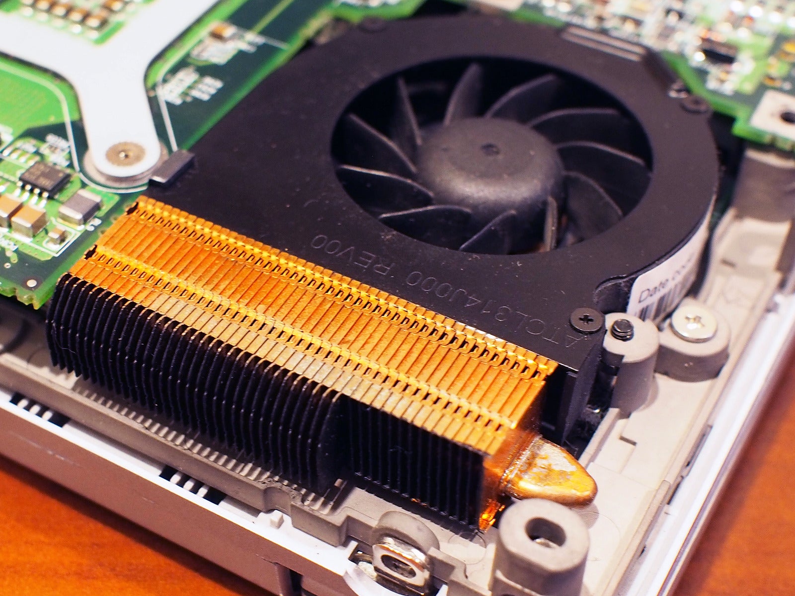 |
| Notebook heat sink |
Compare
that to a cooler with an axial fan. There you have 4-6 heat pipes that can be
viewed as vapour chambers with 2 *
diameter * length as area ( only 2* diameter and not the circumference because
heat exchange at the point where the air hits the heat pipe and leaves the
heat pipe is pretty low.
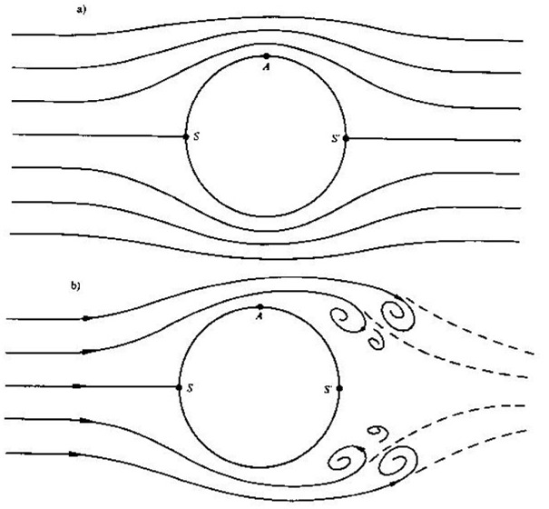 |
| Illustration of turbulent air flow around a round object |
Now add to
this the surface area increase provided by the fins (don't forget to consider
the same flow limitations as before) and the increased air flow provided by
axial coolers and you just made yourself a nice explanation why vapour chambers
are not always ideal. :)
Don't be
too harsh on me, English isn't my mother tongue.